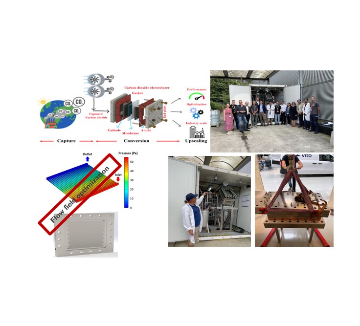
Project Overview
- Target: Characterize gas diffusion electrode (GDE) microstructures and optimize flow configurations for scaled-up industrial CO₂ electrolyzer systems targeting a 50 kW cell stack.
- Approach: Developed 3D finite element simulations coupling fluid dynamics and electrical current pathways to map effective parameters — conductivity, permeability, and active area — across varied carbon particle matrices and electrode architectures.
- Achievements: Validated numerical homogenization metrics against Bruggeman correlations and nickel foam experimental benchmarks, achieving under 10% error margin. Contributed directly to optimizing gas–liquid transport dynamics for the BioRECO₂VER project stack.
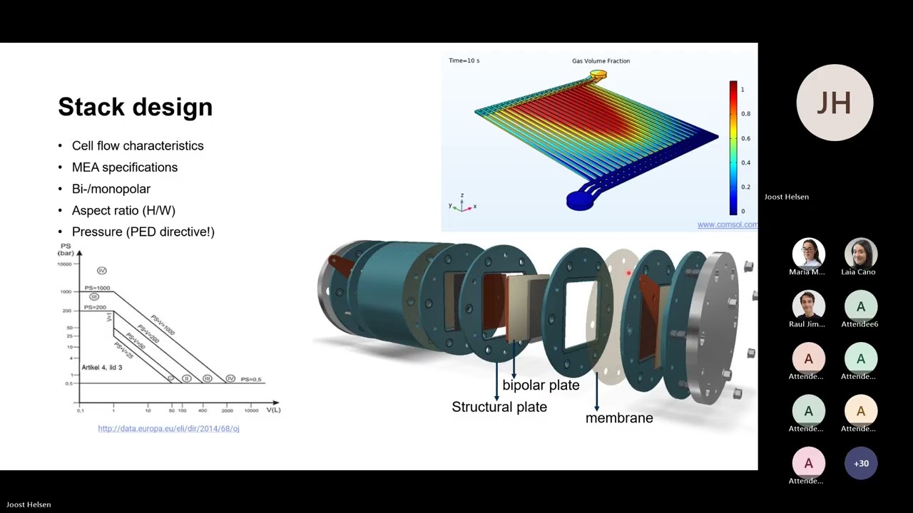
Role of CFD in Stack Design
The CO₂ electrolyzer stack simultaneously handles liquid electrolyte (KOH) and multiple gaseous products — hydrogen, oxygen, carbon monoxide, and ethylene. Managing these complex two-phase flows is not an engineering afterthought; it is the central design problem. Three distinct CFD-driven analyses shaped the final 50 kW stack architecture.
Two-Phase Flow Modeling
Because the system simultaneously handles liquid electrolyte and gaseous products, the internals must manage complex two-phase flows within thin channels.
- Fluid modeling predicts how gas bubbles interact with the liquid stream inside the channel geometry
- Ensures gas moves smoothly without blanketing the catalyst layer — which would otherwise choke the electrochemical reaction
Pressure Drop Balance & Distribution
Fluid mechanics simulations solve a balancing act across flow fields — a challenge that becomes critical at 100-cell stack scale.
- Intra-cell: pressure drop from top to bottom must stay low enough for free liquid circulation without excess pumping power
- Manifold: sufficient drop must be maintained to push flow uniformly into every cell — safely reaching the last cell in a 100-cell stack
Gravity-Driven Evacuation & Orientation
Flow modeling directly dictated the physical positioning of the stack — an outcome that could not have been determined without simulation.
- Buoyancy vs. weight simulations revealed dead zones when the stack was purely horizontal or vertical
- Stack designed at a specific tilted angle — using gravity to drain liquid from the cathode while buoyant gas bubbles rise rapidly from the anode, eliminating stagnant pockets
Video: CFD in Stack Design
From simulation to a 50 kW stack
This video covers the BioRECO₂VER project — including the role of computational fluid dynamics in designing a CO₂ electrolyzer stack from fundamental electrode characterization up to full stack scale. Key themes: two-phase flow management, pressure distribution across a multi-cell manifold, and how simulation results directly informed the physical tilt angle of the final stack assembly.